Préparation JoyPI : Learn
IOT_PY_001_blink⚓
Code⚓
import RPi.GPIO as GPIO
import time
numPin = 18 # la LED ou le buzzer est reliée à la broche 37 (BOARD) ou 18 (BCM)
def setup():
#GPIO.setmode(GPIO.BOARD) # Numérotation physique, sinon GPIO.BCM pour la notation BCMGPIO.setmode(GPIO.BCM)
GPIO.setup(numPin, GPIO.OUT) # La broche est configurée en sortie
GPIO.output(numPin, GPIO.LOW) # On éteint la LED ou le arrête le buzzer
print ('using pin%d'%numPin) # On affiche le n° de broche
def loop():
while True:
GPIO.output(numPin, GPIO.HIGH) # led ou buzz on
print ('...led ou buzz on')
time.sleep(1) # on attend 1 seconde
GPIO.output(numPin, GPIO.LOW) # led ou buzz off
print ('led ou buzz off...')
time.sleep(1)
def destroy():
GPIO.output(numPin, GPIO.LOW) # led off
GPIO.cleanup() # libérer les ressources
if __name__ == '__main__': # Démarrage du programme
setup() try: loop()except KeyboardInterrupt: # Quand 'Ctrl+C' est activé, la méthode destroy est appelée pour mettre fin au programme
destroy() IOT_PY_xxx_buttonbuzzer⚓
Code⚓
#!/#!/usr/bin/pythonimport RPi.GPIO as GPIO
import time
# Broches GPIO button_pin = 27 // BOARD 37
buzzer_pin = 18 // BOARD 12
#BCMGPIO.setmode(GPIO.BOARD)
#lege button_pin als Eingang und buzzer_pin als Ausgang festGPIO.setup(button_pin, GPIO.IN, pull_up_down=GPIO.PUD_UP)
GPIO.setup(buzzer_pin, GPIO.OUT)
try:while True:
#ueberpruefe ob Knopf gedrueckt wirdif(GPIO.input(button_pin) == 0):
#Buzzer einGPIO.output(buzzer_pin, GPIO.HIGH)
else: #Buzzer ausGPIO.output(buzzer_pin, GPIO.LOW)
except KeyboardInterrupt:
GPIO.cleanup()
Réglementaire : Concept important Python⚓
Try - Except
Programmation d'un bouton DI⚓
Niveau à récupérer selon configuration de la broche
Effet rebond
Buzzer - 03⚓
Description⚓
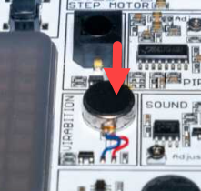
Le module de vibration est un petit moteur qui vibre dès qu'il est alimenté en énergie.
Cette oscillation rend perceptible la fonction du moteur : la vibration.
Ce petit module est parfait pour des applications telles que les alarmes et les notifications.
Connecté à GPIO27.
Exemple : Code⚓
import RPi.GPIO as GPIO
import time

vibration_pin = 27

GPIO.setmode(GPIO.BCM)
GPIO.setup(vibration_pin, GPIO.OUT)

GPIO.output(vibration_pin, GPIO.HIGH)
time.sleep(0.5)
GPIO.output(vibration_pin, GPIO.LOW)

GPIO.cleanup()
import RPi.GPIO as GPIO
import time

vibration_pin = 27

GPIO.setmode(GPIO.BCM)
GPIO.setup(vibration_pin, GPIO.OUT)

GPIO.output(vibration_pin, GPIO.HIGH)
time.sleep(0.5)
GPIO.output(vibration_pin, GPIO.LOW)

GPIO.cleanup()
Relai - 04 -⚓
Présentation⚓
Un relai est un interrupteur électromagnétique utilisé pour commander un circuit d'une source de tension différente de celle qui le commande.
Ainsi, un signal à basse tension (3.3V ou 5V) peut être utilisé pour allumer et éteindre un circuit alimenté par une tension supérieure (12V, 24V, 220V, etc) en continu ou en alternatif..
L'intensité du circuit qui va circuler est limitée par la caractéristique du relai, et bien entendu , la puissance de l'alimentation externe du circuit est totalement indépendante de celle qui alimente votre électronique de commande (RPI, ARDUIINO, ETC)
Attention, la bobine d'un relai ne se pilote pas directement en connectant la tension de 3.3V ou 5V ou encore une sortie GPIO.
Attention : Alimentation et précautions⚓
L'intensité du circuit qui va circuler est limitée par la caractéristique du relai, et bien entendu , la puissance de l'alimentation externe du circuit est totalement indépendante de celle qui alimente votre électronique de commande (RPI, ARDUIINO, ETC)
Attention, la bobine d'un relai ne se pilote pas directement en connectant la tension de 3.3V ou 5V ou encore une sortie GPIO.
Connectique⚓
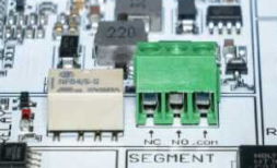
Un relais a deux modes différents. NC et NO. NC signifie "normalement fermé" et NO "normalement ouvert".
En mode "normalement fermé", le circuit est fermé et le courant peut circuler. Dès que la tension de commande est appliquée, le circuit s'ouvre et le circuit est interrompu.
Exemple : Objectif du code C100-04⚓
Vérifier avec une sortie qui passe de l'état haut à l'état bas provoque bien un changement d'état. Nous ne connectons aucune charge sur le relai pour l'instant.
Identifiez l'effet (clic clac)
#!/usr/bin/pythonimport RPi.GPIO as GPIO
import time
Pin = 21 # le relai est activé sur la broche BCM 21 // BOARD = 39
NbCycles = 2
def setup():
GPIO.setmode(GPIO.BCM)
GPIO.setup(Pin, GPIO.OUT) # La broche est configurée en sortie
GPIO.output(Pin, GPIO.LOW) # On s'assure de mettre le relai en mode NC (à vérifier)
# structure boucle infiniedef loop():
# boucle avec un nombre d'itération NbCyclesfor i in range(0, NbCycles):
print('Cycle n°%d'%(i+1))
GPIO.output(Pin, GPIO.HIGH) # On bascule en NO
time.sleep(2)
GPIO.output(Pin, GPIO.LOW) # On bascule en NC
time.sleep(1)
print('fin de la boucle')
destroy()def destroy():
GPIO.output(Pin, GPIO.LOW) # remettre le relai en NC
GPIO.cleanup()
print('Ressources libérées')
if __name__ == '__main__': # Démarrage du programme
setup() try:print('Lancement de la boucle')
loop()except KeyboardInterrupt: # Quand 'Ctrl+C' est activé, la méthode destroy est appelée pour mettre fin au programme
print('Interrompu par l\'utilisateur') # le caractère \ devant ' permet de ne pas mettre fin la chaîne de caractère
destroy()Conseil : GMAO⚓
Familles de pièces concernées : FP38.
Intégration et Nomenclatures :
Capteur tilt⚓
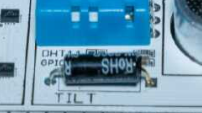 |  |
Le capteur d'inclinaison a deux côtés. Le gauche et le droit.
Si le capteur est incliné vers la gauche, un circuit se ferme et le capteur répond avec un signal GPIO.HIGH.
Si le capteur est incliné dans une autre direction, le circuit s'ouvre et le signal devient un signal GPIO.LOW.
Conseil : Objectif du code C100-05⚓
A l'aide d'une boucle infinie, le programme retourne un message lorsque le capteur est orienté vers la gauche, sinon, il affiche le contraire.
7 Segments - 06⚓
Créer une horloge numérique.⚓
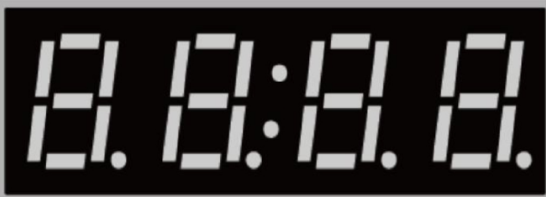 |  |
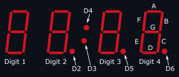
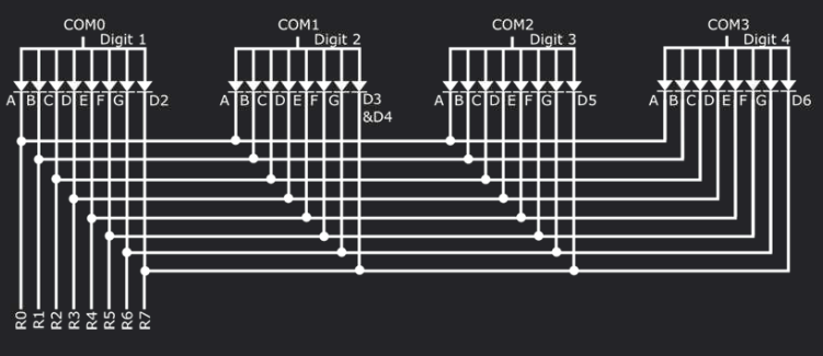
Dans l'affichage par segments, des segments individuels, que vous voyez ici sous forme de tirets, sont commandés pour afficher les différents chiffres.
Selon les segments activés, d'autres chiffres deviennent visibles.
Chaque segment est contrôlé par sa propre broche. En outre, chaque point décimal est également contrôlé par sa propre broche.
Bibliothèques⚓
Pour faciliter le contrôle de notre écran, nous utiliserons un driver, le HT16K33, ainsi qu'une librairie d'Adafruit adaptée au JoyPi Note.
Si l'heure n'est pas correcte plus tard, vous devrez peut-être ajuster l'heure du système de votre Raspberry Pi.
Tapez simplement dans la console l'instruction ci-dessous :
sudo raspi-config
import time
import datetime
from JoypiNote_adafruit_ht16k33.segments import Seg7x4
import board
You may wonder how we control the segment display without using the GPIOs? Even if the display is connected via the GPIO pins, it is controlled via a protocol called I2C.
I2C is a serial communication type. This means that the data to be transmitted is sent individually, bit by bit, via a data line (the SDA line). I2C is a synchronous transmission type. So, the bits are synchronized over a clock line (the SCL line) between the transmitter and receiver. Fortunately, we have a library that handles the communication process for us. So, we don't have to deal with this complex subject in detail.
Next, we configure our segment display. This communicates on the I2C address 0x70
Now, we can use "segment" whenever we want to call a function of the library. Next, we initialize the display so it knows we want to use it. We do this with the segment.begin() command.
Now, that our display is ready, we first retrieve the current time and divide it into hours, minutes and seconds:
Now, we take our hours and minutes and pass them to our display. 2 digits for the hours and two digits for the minutes thus fill our 4-digit segment display.
Let's also activate the colon in the middle so that we can see the separation between hours and minutes. We can do this with the set_colon(true)-function
But just because we have set the data, it does not mean that it will work. We have only stored the data in our software, but now we need to transfer it to the display. We can do this with the write_display()-statement.
Now let's wait a quarter of a second before we have our instructions repeated:
Great! You have successfully completed this lesson and can now control the segment display yourself. Run the script and look at the time. Try to change the single digits and show different numbers. You can also turn the colon on or off.
Attention : Protocole I2C⚓
Le GPIO n'est pas suffisant pour gérer toutes les lignes de communication des segments de l'afficheur, il faut passer par un protocole I2C qui utilise très peu de broches pour communiquer avec une connectique et une électronique pouvant être très complexe.
I2C est un type de communication série : les données à transmettre sont envoyées individuellement, bit par bit, via une ligne de données (dans ce cas, la ligne SDA). I2C est un mode de transmission synchrone. Les bits sont donc synchronisés entre l'émetteur et le récepteur via une ligne d'horloge (ici la ligne SCL).
Plusieurs appareils peuvent être connectés aux lignes SDA et SCL.
Ainsi, au moyen d'une adresse au début de la communication, il est possible de déterminer avec quelle puce nous voulons communiquer.
L'afficheur 7 Segments communique à l'adresse I2C 0x70
i2c = board.I2C()
segment = Seg7x4(i2c)
Nous pouvons maintenant l'utiliser le segment chaque fois que nous voulons appeler une fonction de la bibliothèque.
Si nous avons déjà utilisé l'afficheur de segments, il se peut que quelque chose y soit déjà écrit. Pour en être sûr, nous devons d'abord effacer l'affichage avant de commencer à l'utiliser :
try:while(True):
now = datetime.datetime.now()
hour = now.hour
minute = now.minute
second = now.second
Nous prenons maintenant nos heures et nos minutes et les transmettons à notre écran. 2 chiffres pour les heures et 2 chiffres pour les minutes remplissent ainsi notre écran à 4 chiffres.
En premier, on passe les heures :
        segment[0] = str(int(hour / 10))
        segment[1] = str(hour % 10)
puis les minutes
        segment[2] = str(int(minute / 10))
        segment[3] = str(minute % 10)
Activons et désactivons toujours le point au milieu du segment, à chaque seconde, afin d'avoir un retour visuel sur les secondes...
segment.colon = bool(second % 2)
Attendons 1s
time.sleep(1)
Dans notre exception à l'instruction try, nous effaçons l'affichage du segment de manière à ce qu'il soit éteint lorsque le programme se termine.
except:segment.fill(0)
Conseil : Objectif du code C100-06⚓
a
Joystick - 07⚓
 |
Le joystick a quatre directions différentes : Avant, Arrière, Gauche et Droite. Chaque fois que vous inclinez le joystick dans l'une de ces directions, la broche GPIO responsable de cette direction est activée.
La position du joystick est indiquée par deux axes. L'axe X indique la position horizontale (gauche/droite) et l'axe Y indique la position verticale (avant/arrière).
En fonction de la direction dans laquelle le joystick a été incliné, les valeurs des deux axes du joystick changent également. Il est ainsi possible de déterminer clairement sa position.
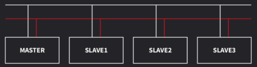
SPI est un bus de données sériel comme I2C et fonctionne selon le principe maître-esclave (master-slave). Pour ce faire, les fils suivants sont utilisés :
- SCLK : la ligne d'horloge (spécifie l'horloge à communiquer),
- MOSI (Master Out Slave In) : le Raspberry Pi envoie des données à l'ADC,
- MISO (Master In, Slave Out) : l'ADC envoie des données au Raspberry Pi
- SS (Slave Select) : utilisé pour sélectionner l'ADC.
Bibliothèques⚓
Nous avons besoin de la bibliothèque time et de la bibliothèque spidev, que nous pouvons utiliser pour lire les données analogiques à l'aide du convertisseur ADC (analogique-numérique). Ce convertisseur communique au moyen d'une interface périphérique série SPI (Serial Peripheral Interface)
import time
import spidev
Paramétrage du port SPI⚓
Pour pouvoir lire les données analogiques du joystick, nous devons d'abord définir le port SPI et la vitesse de lecture :
spi = spidev.SpiDev()
spi.open(0,1)
spi.max_speed_hz=1000000
Méthode de lecture des données.⚓
Ensuite, nous définissons la méthode qui récupère les données analogiques via SPI et nous les renvoie.
def ReadChannel(channel):
    adc = spi.xfer2([1,(8+channel)<<4,0])
    data = ((adc[1]&3) << 8) + adc[2]
    return data
Corps du programme de test⚓
Comme nous l'avons déjà mentionné, notre joystick se compose de deux axes. L'axe X est connecté au canal 1 et l'axe Y au canal 0. Nous fixons des seuils pour détecter les actions Gauche-Droite, Haut-Bas.
LED (Breadboard) - 08⚓
Vibration⚓
Description⚓
Le buzzer est un composant qui émet un son dès qu'il est alimenté.
Le buzzer possède deux broches : GND et GPIO18, ce qui signifie que le buzzer est connecté à la broche GPIO 18 (mode GPIO.BCM) du Joy-Pi Note afin d'être contrôlé. Il est également connecté à la connexion GND du Joy-Pi Note pour fermer le circuit.
Exemple : Code⚓
import RPi.GPIO as GPIO
import time

vibration_pin = 27

GPIO.setmode(GPIO.BCM)
GPIO.setup(vibration_pin, GPIO.OUT)

GPIO.output(vibration_pin, GPIO.HIGH)
time.sleep(0.5)
GPIO.output(vibration_pin, GPIO.LOW)

GPIO.cleanup()
Servo - 09⚓
Permettre la rotation de petits objets ou composants.
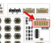
Connecter le servo à l'aide de son câble à l'interface prévue :
Next, we have a long class with different functions. Adopt these first, then we'll go step by step through each function. First, we need the sg90 class with the init initial function:
Now, follows the cleanup() function, which moves the servo motor to its initial position after we used it.
Now, let's create a function that will determine the current direction for us:
The next function is responsible for setting the direction:
Let's now use the setdirection function, which takes the direction and speed information to turn the servo motor.
So now we have created the class sg90. This contains various functions, such as the init function, which initializes the software, the setdirection-function, which is responsible for moving the motor and the cleanup()-function, which is responsible for moving back to the starting position.
That was quite a lot, wasn't it? But the only code that is important for us is in the setdirection-function. Here we pass the direction and speed to the function which controls the servo motor for us.
Now first call the sg90 class and initialize it with 0 degrees to define the motor:
So, the code we have now created first configures the object s as an sg90 class. We initialize this with 0 as our initial servo direction. We then perform a rotation to the left, specifying a rotation angle of 100 degrees and a speed of 80%. This is followed by a rotation to the right, also with a rotation angle of 100 degrees and a speed of 80%. After that, we wait half a second before we finish our execution with s.cleanup().
Conseil : Objectif du code C100-09⚓
a
Moteur pas à pas 100-010⚓
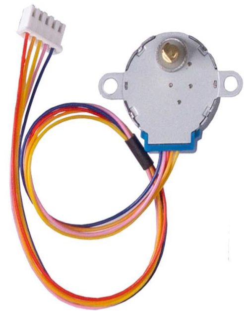 |  |
In contrast to the servomotor, the stepper motor is very precise. It works, as the name suggests, in steps. We can tell this motor exactly by how many steps it should move. In addition, the stepper motor can rotate 360 degrees and, unlike the servo motor, has no angle limitation.
In this lesson, we will write a library that controls the stepper motor and moves it in steps or by a specified angle. Stepper motors usually need a motor driver. Without this, they will not work. The Joy-Pi Note already has a built-in stepper motor driver, so we don't need to connect any additional components here. First, connect the stepper motor to your Joy-Pi Note.
As in the previous lessons, we first import the RPi.GPIO and the time library. But in addition, this time we will import the math library, which will help us to perform mathematical calculations in Python.
First define the stepper motor class together with the initialization function which takes care of the configuration of the GPIO pins:
Now that we have imported all the necessary libraries, we can write our own library. This one might look a bit long, but don't worry! As in the examples before, we'll look at the code first and then explain exactly what happens.
Now, we create the first phase of the stepper motor movement:
def Step1(self):
GPIO.output(self.pin_D, True)
time.sleep(self.interval)
GPIO.output(self.pin_D, False)
Conseil : Objectif du code C100-10⚓
import time
import RPi.GPIO as GPIO
import math
class Stepmotor:
def __init__(self):
# set GPIO modeGPIO.setmode(GPIO.BCM)
# These pins are used by the Raspberry Piself.pin_A = 5
self.pin_B = 6
self.pin_C = 13
self.pin_D = 25
self.interval = 0.0011
# Define pins as outputGPIO.setup(self.pin_A,GPIO.OUT)
GPIO.setup(self.pin_B,GPIO.OUT)
GPIO.setup(self.pin_C,GPIO.OUT)
GPIO.setup(self.pin_D,GPIO.OUT)
GPIO.output(self.pin_A, False)
GPIO.output(self.pin_B, False)
GPIO.output(self.pin_C, False)
GPIO.output(self.pin_D, False)
def Step1(self):
GPIO.output(self.pin_D, True)
time.sleep(self.interval)
GPIO.output(self.pin_D, False)
def Step2(self):
GPIO.output(self.pin_D, True)
GPIO.output(self.pin_C, True)
time.sleep(self.interval)
GPIO.output(self.pin_D, False)
GPIO.output(self.pin_C, False)
def Step3(self):
GPIO.output(self.pin_C, True)
time.sleep(self.interval)
GPIO.output(self.pin_C, False)
def Step4(self):
GPIO.output(self.pin_B, True)
GPIO.output(self.pin_C, True)
time.sleep(self.interval)
GPIO.output(self.pin_B, False)
GPIO.output(self.pin_C, False)
def Step5(self):
GPIO.output(self.pin_B, True)
time.sleep(self.interval)
GPIO.output(self.pin_B, False)
def Step6(self):
GPIO.output(self.pin_A, True)
GPIO.output(self.pin_B, True)
time.sleep(self.interval)
GPIO.output(self.pin_A, False)
GPIO.output(self.pin_B, False)
def Step7(self):
GPIO.output(self.pin_A, True)
time.sleep(self.interval)
GPIO.output(self.pin_A, False)
def Step8(self):
GPIO.output(self.pin_D, True)
GPIO.output(self.pin_A, True)
time.sleep(self.interval)
GPIO.output(self.pin_D, False)
GPIO.output(self.pin_A, False)
def turn(self,count):
for i in range (int(count)):
self.Step1()
self.Step2()
self.Step3()
self.Step4()
self.Step5()
self.Step6()
self.Step7()
self.Step8()
def close(self):
# Clean up GPIO pinsGPIO.cleanup()
def turnSteps(self, count):
# Rotate by n stepsfor i in range (count):
self.turn(1)
def turnDegrees(self, count):
# Rotate by n degreesself.turn(round(count*512/360,0))
def turnDistance(self, dist, rad):
self.turn(round(512*dist/(2*math.pi*rad),0))
print("Movement started")
motor = Stepmotor()
print("Single step")
motor.turnSteps(1)
time.sleep(0.5)
print("20 steps")
motor.turnSteps(20)
time.sleep(0.5)
print("quarter turn")
motor.turnDegrees(90)
time.sleep(0.5)
print("full rotation")
motor.turnDegrees(360)
print("Movement stopped")
motor.close()
Matrice LED RGB100-011⚓
|  |

Le module 8x8 (8 colonnes et 8 lignes) est composé de 64 LED au total. Les LED utilisées sont des WS2812B, qui sont très populaires et particulièrement faciles à utiliser
A VERIFIER (cf https://github.com/rm-hull/luma.led_matrix/)
RVB signifie rouge, vert et bleu. On mélange ces couleurs pour obtenir n'importe quelle couleur.
D'une part, nous avons besoin de la bibliothèque Time, que nous connaissons déjà. D'autre part, nous avons besoin de la bibliothèque rpi_ws281x. Il s'agit d'une bibliothèque spécialement conçue pour le Raspberry Pi et Python, qui nous permet de contrôler nos LED WS2812B.
import time
import spidev
Attention : INSTALLATION SI ECHEC⚓
First we need to import a few libraries. On the one hand, we need the time library, which is already known to us. On the other hand, we need the rpi_ws281x library. This is a library especially for the Raspberry Pi and Python, which allows us to control our WS2811 LEDs.
Now we have to configure some parameters for our LEDs. First, we determine the number of LEDs we have available. That is 64 LEDs in total.
Then we define to which GPIO pin our module is connected. In our case, this is the GPIO pin 12.
Now we determine the frequency with which our LEDs are controlled. The optimal frequency for our LEDs is 800000 Hz.
We can now also configure the brightness. This can be set between 0 and 255. Let's start with a value of 10 because our module can get very bright!
The LEDs in our Joy-Pi Note are not inverted. We define this as well.
Since we control our module via GPIO, we do not need any channels. Therefore, we set the channels to 0.
That was quite a lot to configure, wasn't it? We have completed the configuration for now. Now we come to our first functions. These will control our LEDs. But let's go step by step! Our first function will go step by step through each LED and clear them. We will use this to reset the output on our module.
The second function is called theaterChase. With it, we animate an LED running light.
The third function we call wheel. Along with this function, we also use a function called rainbow. We use these two functions that run through all the LEDs and run through the colors between 0 and 255 and let the colors create a rainbow pattern.
Now that we have created all our functions, we can take care of our main function. First, we define our RGB LED object with the Pixel-Strip function.
Then we initialize our module using the begin() function.
Now, it's time to use our functions to activate our LED module.
First, we use our colorWipe function. With it, we set all LEDs one after the other to read, then to green and then to blue.
Now, we come to our theaterChase function. Here the LEDs track each other in a horizontal direction. We start with white, then move to red and finally switch to blue.
Finally, we use our rainbow function:
Nous devons d'abord importer quelques bibliothèques. D'une part, nous avons besoin de la bibliothèque Time, que nous connaissons déjà. D'autre part, nous avons besoin de la bibliothèque rpi_ws281x. Il s'agit d'une bibliothèque spécialement conçue pour le Raspberry Pi et Python, qui nous permet de contrôler nos LED WS2811.
Nous devons maintenant configurer quelques paramètres pour nos LEDs. Tout d'abord, nous déterminons le nombre de LEDs dont nous disposons. Il s'agit de 64 LEDs au total.
Ensuite, nous définissons à quelle broche GPIO notre module est connecté. Dans notre cas, il s'agit de la broche GPIO 12.
Nous déterminons maintenant la fréquence à laquelle nos LED sont contrôlées. La fréquence optimale pour nos LED est de 800000 Hz.
Nous pouvons maintenant configurer la luminosité. Celle-ci peut être réglée entre 0 et 255. Commençons par une valeur de 10 car notre module peut devenir très lumineux !
Les LEDs de notre Joy-Pi Note ne sont pas inversées. C'est ce que nous définissons également.
Puisque nous contrôlons notre module via GPIO, nous n'avons pas besoin de canaux. C'est pourquoi nous mettons les canaux à 0.
Cela fait beaucoup de choses à configurer, n'est-ce pas ? Nous avons terminé la configuration pour l'instant. Nous en arrivons maintenant à nos premières fonctions. Celles-ci contrôleront nos LEDs. Mais allons-y pas à pas ! Notre première fonction va parcourir pas à pas chaque LED et les effacer. Nous l'utiliserons pour réinitialiser la sortie de notre module.
La deuxième fonction s'appelle theaterChase. Elle nous permet d'animer un feu de circulation à DEL.
La troisième fonction s'appelle wheel. Avec cette fonction, nous utilisons également une fonction appelée rainbow (arc-en-ciel). Nous utilisons ces deux fonctions pour parcourir toutes les DEL et les couleurs entre 0 et 255 et laisser les couleurs créer un motif d'arc-en-ciel.
Maintenant que nous avons créé toutes nos fonctions, nous pouvons nous occuper de notre fonction principale. Tout d'abord, nous définissons notre objet LED RVB avec la fonction Pixel-Strip.
Ensuite, nous initialisons notre module à l'aide de la fonction begin().
Il est maintenant temps d'utiliser nos fonctions pour activer notre module LED.
Tout d'abord, nous utilisons la fonction colorWipe. Avec elle, nous mettons toutes les LED, l'une après l'autre, en mode lecture, puis en mode vert et enfin en mode bleu.
Nous en venons maintenant à notre fonction theaterChase. Ici, les DEL se suivent les unes les autres dans une direction horizontale. Nous commençons par le blanc, puis nous passons au rouge et enfin au bleu.
Enfin, nous utilisons notre fonction rainbow :
Conseil : Objectif du code C100-10⚓
import time
from rpi_ws281x import PixelStrip, Color
# LED module configuration:LED_COUNT = 64 # Number of LEDs
LED_PIN = 12 # GPIO pin used
LED_FREQ_HZ = 800000 # Signal frequency
LED_DMA = 10 # DMA channel
LED_BRIGHTNESS = 10 # Brightness between 0 and 255
LED_INVERT = False
LED_CHANNEL = 0
RIGHT_BORDER = [7,15,23,31,39,47,55,63]
LEFT_BORDER = [0,8,16,24,32,40,48,56]
def colorWipe(strip, color, wait_ms=50):
for i in range(strip.numPixels()):
strip.setPixelColor(i, color)
strip.show()
time.sleep(wait_ms / 1000.0)
def theaterChase(strip, color, wait_ms=50, iterations=10):
for j in range(iterations):
for q in range(3):
for i in range(0, strip.numPixels(), 3):
strip.setPixelColor(i + q, color)
strip.show()
time.sleep(wait_ms / 1000.0)
for i in range(0, strip.numPixels(), 3):
strip.setPixelColor(i + q, 0)
def wheel(pos):
if pos < 85:
return Color(pos * 3, 255 - pos * 3, 0)
elif pos < 170:
pos -= 85
return Color(255 - pos * 3, 0, pos * 3)
else:pos -= 170
return Color(0, pos * 3, 255 - pos * 3)
def rainbow(strip, wait_ms=20, iterations=1):
for j in range(256 * iterations):
for i in range(strip.numPixels()):
strip.setPixelColor(i, wheel((i + j) & 255))
strip.show()
time.sleep(wait_ms / 1000.0)
# Initialize NeoPixel object with appropriate configurationstrip = PixelStrip(LED_COUNT, LED_PIN, LED_FREQ_HZ, LED_DMA, LED_INVERT, LED_BRIGHTNESS, LED_CHANNEL)
strip.begin()
# Start animationsprint("colorWipe-Animation")
colorWipe(strip, Color(255, 0, 0)) # Red
colorWipe(strip, Color(0, 255, 0)) # Green
colorWipe(strip, Color(0, 0, 255)) # Blue
print("theaterChase-Animation")
theaterChase(strip, Color(127, 127, 127)) # White
theaterChase(strip, Color(127, 0, 0)) # Red
theaterChase(strip, Color(0, 0, 127)) # Blue
print("rainbow-Animation")
rainbow(strip)
print("Turn off LEDs")
colorWipe(strip, Color(0, 0, 0), 10)
Présence - 12⚓
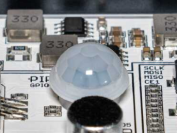
Détecteur de présence (PIR)⚓
Le capteur infrarouge passif (PIR) détecte les changements dans la quantité de rayonnement infrarouge provenant de l'environnement. Ce rayonnement dépend de la température et des propriétés de la surface des objets qui se trouvent devant lui. Si un objet, par exemple une personne, s'approche du capteur, les variations de température peuvent être mesurées à cet endroit. |
|

Le capteur PIR est principalement utilisé pour détecter les mouvements. Dans cette leçon, nous apprendrons à contrôler le capteur et, en fonction de son signal, à activer une lumière RVB. En d'autres termes, nous allons construire un détecteur de mouvement
Librairies utilisées :⚓
- RPi.GPIO
- time
import RPi.GPIO as GPIO
import time
Configuration⚓
Broche BCM du capteur PIR : 23.
motion_pin = 23
GPIO.setmode(GPIO.BCM)
GPIO.setup(motion_pin, GPIO.IN)
Partie 1⚓
Dans une boucle, nous testons si aucun mouvement n'a été détecté par le capteur. Un message est affiché
try:while True:
if(GPIO.input(motion_pin) == 0):
print("Pas de mouvement ...")
Partie 2⚓
Nous vérifions le signal du capteur PIR toutes les 0,1 secondes. Si nous détectons un mouvement, nous affichons un message via un print sur la console.
elif(GPIO.input(motion_pin) == 1):
            print("Mouvement détecté")

except KeyboardInterrupt:
    GPIO.cleanup()